What is a MOSFET and what is it used for Circuit Diagram By using MOSFETs in inverter circuits, engineers can design power-efficient systems that meet the requirements of various electronic devices. Components Required for an Inverter Circuit. An inverter circuit is commonly used to convert DC power to AC power, enabling the use of electronic devices that require alternating current. How to Use MOSFET as a Switch. To use a MOSFET as a switch, you need to ensure that the gate-source voltage (Vgs) is higher than the source voltage. When the gate is connected to the source (Vgs=0), the MOSFET remains off. Take the IRFZ44N, a "standard" MOSFET, as an example. This MOSFET only turns on when Vgs ranges between 10V and 20V.
The final MOSFET gate circuit looks like the below figure. The gate of a MOSFET does not normally draw any current (apart from the small leakage current), but when used in switching applications where it should be turned on and off quickly, the gate capacitance has to be charged and discharged rapidly.

PDF ECE 255, MOSFET Circuits Circuit Diagram
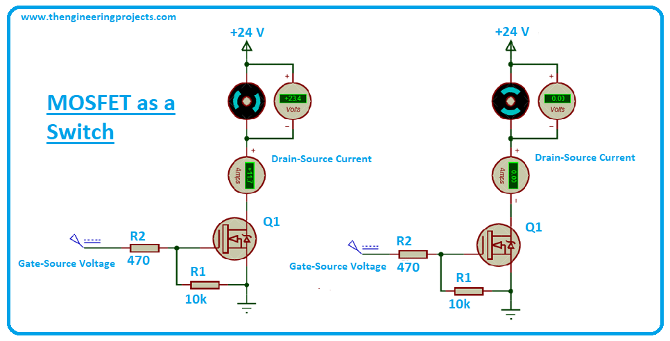
Consider a MOSFET with a Drain to Source Resistance of 0.1Ω. In the above case i.e., a 12W LED driven by a 12V supply will lead to a drain current of 1A. Hence the power dissipated by the MOSFET is P = I 2 * R = 1 * 0.1 = 0.1W. This seems to be a low value but if you drive a motor using the same MOSFET, the situation is slightly different.

This type of MOSFET is generally used in logic circuits. Enhancement type MOSFET. In Enhancement type of MOSFETs, the device remains OFF at zero Gate voltage. To turn on the MOSFET , we must provide a minimum Gate to Source voltage (Vgs Threshold voltage). But, the drain current is highly dependable on this gate-to-source voltage, if the Vgs is
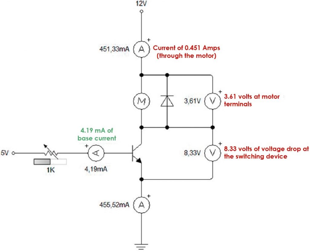
Analysis of MOSFET as a Switch with Circuit Diagram, Example
Early MOS digital circuits were made using p-MOSFET. But with the advancements of microelectronics technology the threshold voltage of MOS can be controlled and an MOS technology becomes dominant, as the majority carries of n-MOS, i.e electrons are twice faster than the holes, the majority carriers of p-MOS, so the inverter circuits also using n-MOS technology until CMOS technology arrived.
