How to Use Any Relay With Your Arduino the Safe Way Circuit Diagram A 2-channel relay module can control two appliances independently. An 8-channel relay module is useful for more complex projects, such as home automation systems. Each relay in a multi-channel module works independently, so you can control them individually using separate Arduino pins.

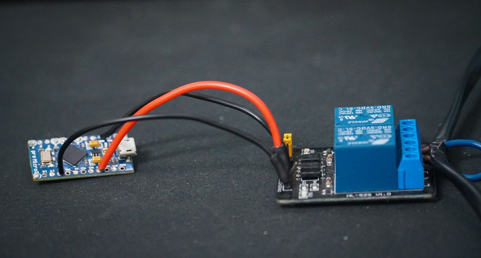
When the temperature crosses the predefined max temperature value mentioned in the Arduino code the relay 1 and the relay 2 turns on. When the temperature becomes lower than the predefined min temperature value mentioned in the Arduino code the relay 1 and the relay 2 turns off. LDR Control. An LDR is fitted on the PCB to sense the ambient light. Any Arduino Microcontroller Board: You can use any Arduino board for this project. We picked an Arduino Pro Micro because they are nice and small, but an Uno would work just as well. A 5V Active Low Relay Board: You can find relay board with one, two, four, and eight channels. Choose one that matches the number of electrical devices it needs to The simplest solution for on/off Home Automation is to use the free pfodDesigner to design your control for upto 4 switches and then use a Arduino Uno + Cheap/Simple Wifi Shield + DFROBOT Relay Shield for Arduino V2.1 powered by a USB power supply and controlled by pfodApp and, if switching mains power, have an electrician wire it in.
How to Make Smart Home Using Arduino Control Relay Module Circuit Diagram
This Arduino code is designed to control a relay using a momentary button. It includes debouncing logic to ensure the button press is stable before triggering any action. Step-by-Step Explanation. 1. Read Button State: int reading = digitalRead(buttonPin); - Reads the current state of the button pin (`HIGH` or `LOW`). 2. Reset Debouncing Timer: Connecting LDR to Arduino UNO. Connect the A0 analog pin of Arduino to any pin of the LDR. Connect the other pin of the LDR to the 5v of Arduino.; Then connect the 10k resistor from GND to A0 of Arduino.; Connecting Relay to Arduino UNO. Connect the digital pin 8 of Arduino to the Signal pin of the relay module.; Connect the 5v from Arduino to the Power connection of the relay module.
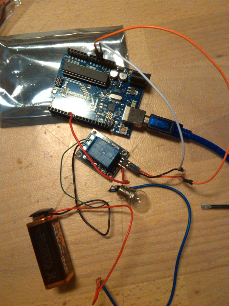
2.Connect the power supply and set up the project. Then connect the control pins. Finally connect the load (circuit board that you'll control using a relay module). 3.Power up your arduino using a power supply or USB cable. 4.Write the code. One code example is as follows: // Define the Arduino pin connected to the relay module control pin
Driving a Relay With an Arduino : 9 Steps Circuit Diagram
When the Arduino sends a signal to the relay, the electromagnet activates and changes the state of the relay's contacts, either turning a device on or off. Use cases of Relay Module. Relays are commonly used in home automation to control high-power devices: Lighting Control: Turn lights on/off remotely or based on sensor inputs.
