Additional Resources Cerebro Wireless Optogenetics System 204 Circuit Diagram This video shows three different ways we solder electronic components to printed circuit boards: reflow, wave solder, and hand soldering.
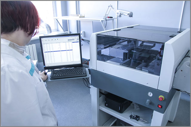
Reflow soldering, on the other hand, is better suited for SMD-heavy assemblies, providing precise and consistent solder joints with minimal thermal stress on components. When choosing between wave soldering and reflow soldering, consider factors such as component types, production volume, PCB complexity, budget, equipment, and quality requirements.

Reflow, wave and hand soldering Circuit Diagram
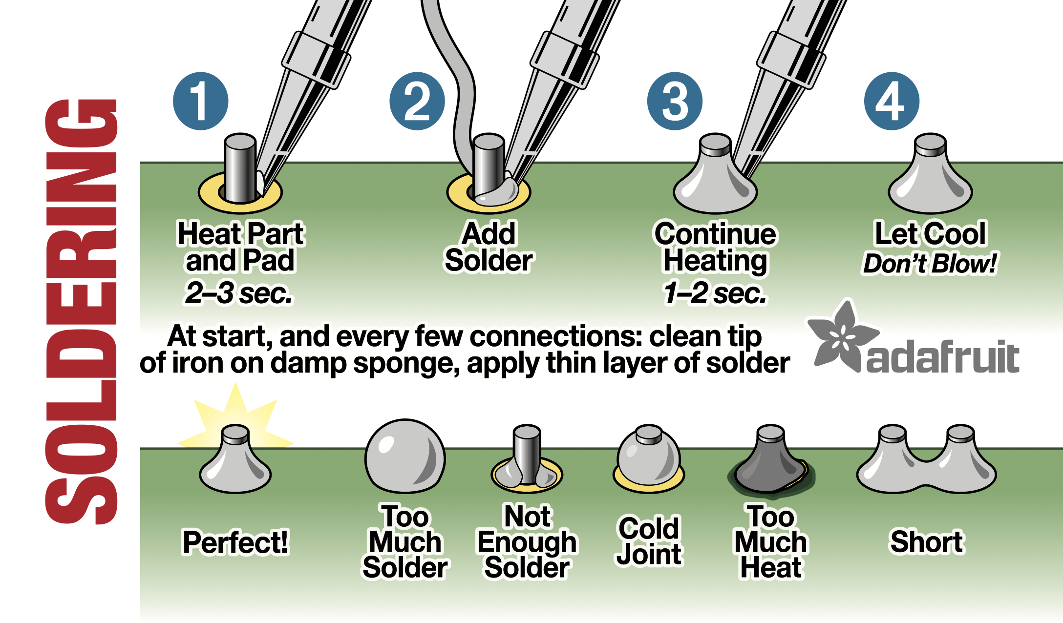
It is a well-known fact that hand soldering is a much less controlled process than the SMT process. If it handled correctly, hand soldering could introduce some quality issues. Here are some tips for hand soldering: The solder iron needs to be kept clean. The black crud built up from metal oxide and charred flux should be removed frequently.
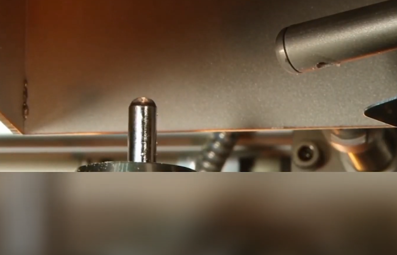
Hand soldering and robotic soldering are used for through hole components while wave soldering and reflow soldering are used for surface mount components. Robotic soldering is now being used to replace the time-consuming hand soldering. Reflow soldering is the commonly used technology for surface mount components which also uses wave soldering.
Reflow Soldering Guide. Process, Oven and Advantages Circuit Diagram
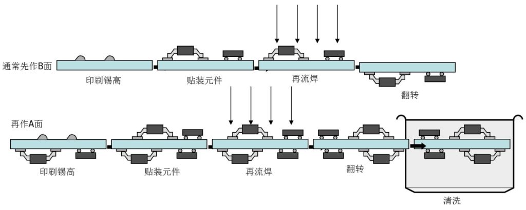
The Procedure of Reflow Soldering. Reflow soldering involves several critical preparation and assembly steps to ensure precise placement and bonding of components. Here is a detailed overview of the steps you need to follow in a reflow soldering station. 1. Preparation. The first stage is preparing the board and components for soldering.